
Inter-VLAN routing: how traffic crosses between VLANs
Why two VLANs cannot reach each other at Layer 2, and how one Layer-3 interface per VLAN — a router subinterface or a switch SVI — routes traffic between them.
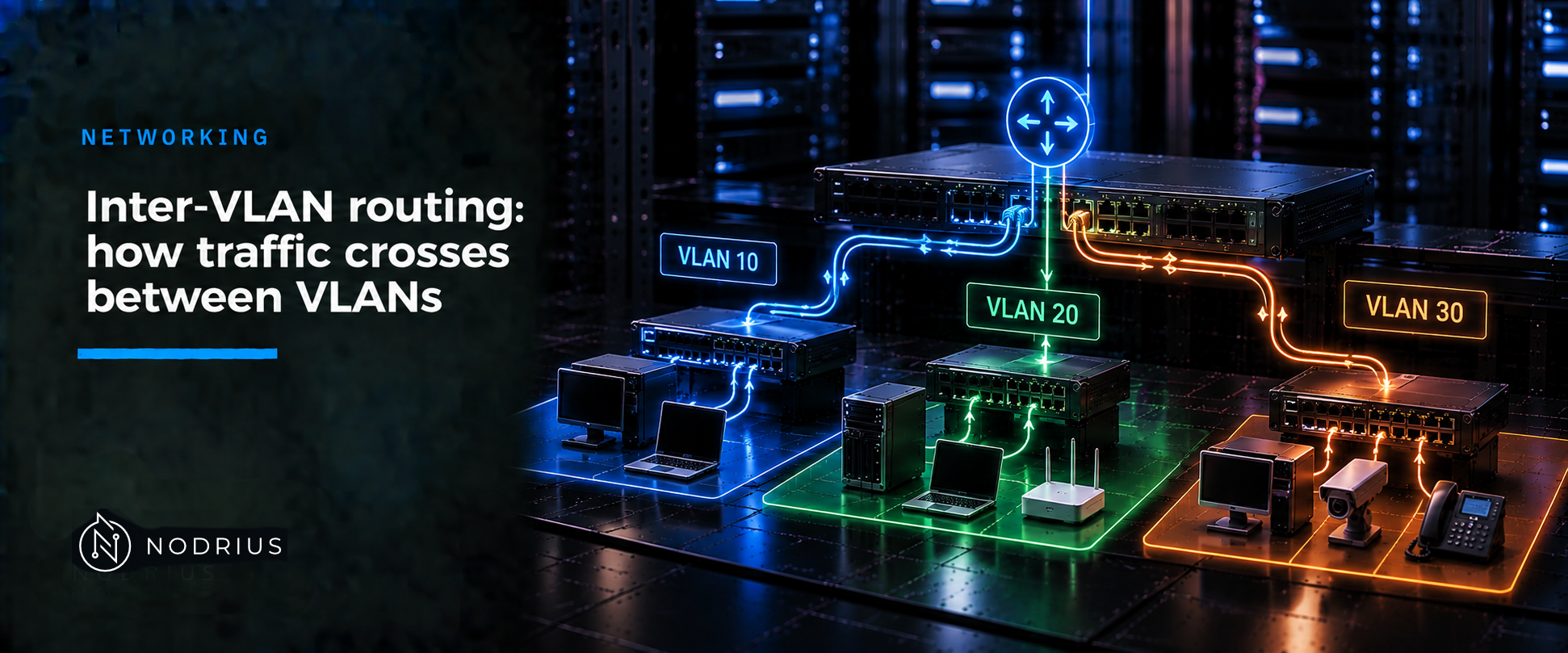
A VLAN is a Layer-2 broadcast domain, and Layer-2 forwarding never crosses one: hosts in different VLANs are on different IP subnets and their frames stop at the boundary. Inter-VLAN routing gives each VLAN one Layer-3 interface, in that subnet, to act as its default gateway — a subinterface on an external router or a switch virtual interface (SVI) on a Layer-3 switch. Hosts send off-subnet traffic to that gateway; the device forwards on the destination IP and writes a new Layer-2 header for the destination VLAN. The IP addresses never change.
The mental model
              VLAN 10                  Layer-3 device                   VLAN 20
          192.0.2.0/24                                              198.51.100.0/24

  PC1 .10 ─── access ──┐            ┌── gateway interface ──┐            ┌── access ──── PC3 .10
                       ├─ switch A ─┤  VLAN 10: 192.0.2.1   ├── trunk ───┤
  PC2 .11 ─── access ──┘            │  VLAN 20: 198.51.100.1│            └── access ──── PC4 .11
                                    └───────────────────────┘

  PC1 sends to gateway 192.0.2.1                (frame in VLAN 10)
        └─ routing decision on the destination IP
           └─ 198.51.100.0/24 is directly connected
              └─ new Layer-2 header for VLAN 20   (IP addresses unchanged)
                 └─ PC3 receives the frame
The one idea: routing happens between two Layer-3 interfaces, not “on the VLAN”, so each VLAN needs exactly one gateway interface; the methods differ only in where it lives.
Terminology
- Inter-VLAN routing — Layer-3 forwarding between two VLANs, which are separate Layer-2 broadcast domains.
- SVI (Switch Virtual Interface) — the Layer-3 interface a switch creates for a VLAN (
interface Vlan<id>); Cisco calls it the interface that “represents a VLAN of switch ports as one interface to the routing function”. One SVI per VLAN. - Subinterface — a Layer-3 interface on a physical router port (
GigabitEthernet0/0/0.10), matched to a VLAN byencapsulation dot1q <vlan-id>. - Router-on-a-stick — one router link carrying several VLANs as 802.1Q subinterfaces.
- Routed port — a switch port in Layer-3 mode (
no switchport), not tied to a VLAN. - Connected route — the route a device installs for a subnet on its own interface; it makes the other VLAN reachable without a routing protocol.
How the crossing happens, step by step
- Each VLAN is one broadcast domain and one IP subnet; a switch forwards only inside its VLAN, so hosts in different VLANs are invisible to each other at Layer 2.
- Give each VLAN one Layer-3 interface in its subnet — an SVI on a Layer-3 switch, or a subinterface on a router reached over a trunk; that address is the hosts’ default gateway.
- Because the interface holds an address in the subnet, the device installs a connected route; no routing protocol is needed for a directly attached VLAN.
- A host finds the destination off-link and sends the frame to its gateway (the L1 decision); the frame arrives on the Layer-3 interface for VLAN 10.
- The device strips the Layer-2 header, matches the connected route for VLAN 20, writes a new Layer-2 header and forwards; the IP header is untouched, only the link-layer header is rewritten hop by hop.
How it is built, and how to check it
The three methods differ only in where the gateway interface lives; a Layer-2-only switch needs an external Layer-3 device.
| Method | Where the gateway lives | Trade-off |
|---|---|---|
| Router-on-a-stick | subinterfaces on one external router link | reuses an L2-only switch; all inter-VLAN traffic shares that one link |
| SVIs on a Layer-3 switch | one interface Vlan<id> per VLAN on the switch |
the common campus design; the switch is the gateway for every VLAN |
| Legacy, one router port per VLAN | one physical router interface per VLAN | no trunk needed; needs a router port per VLAN, so it scales poorly |
Reference platform: Cisco IOS-XE. The concepts are portable; this syntax is not.
! --- Option A: Layer-3 switch, one SVI per VLAN ---
ip routing
!
vlan 10
 name USERS
vlan 20
 name SERVERS
!
interface GigabitEthernet1/0/1
 switchport mode access
 switchport access vlan 10
interface GigabitEthernet1/0/2
 switchport mode access
 switchport access vlan 20
!
interface Vlan10
 ip address 192.0.2.1 255.255.255.0
 no shutdown
interface Vlan20
 ip address 198.51.100.1 255.255.255.0
 no shutdown

! --- Option B: router-on-a-stick (external router, trunk to the switch) ---
! switch side:  interface GigabitEthernet1/0/24 / switchport mode trunk
!
interface GigabitEthernet0/0/0
 no ip address
 no shutdown
!
interface GigabitEthernet0/0/0.10
 encapsulation dot1q 10
 ip address 192.0.2.1 255.255.255.0
!
interface GigabitEthernet0/0/0.20
 encapsulation dot1q 20
 ip address 198.51.100.1 255.255.255.0
Warnings. no switchport puts a port into Layer-3 mode by shutting it down and re-enabling it, and the port’s Layer-2 configuration can be lost. Enabling ip routing on a former Layer-2 switch starts forwarding between subnets that could not reach each other and can change management reachability. Changing or removing an SVI address that is a VLAN’s default gateway cuts that VLAN off. switchport mode trunk on a live access port also drops its traffic.
Verify by inspection: show ip route should list a connected route per VLAN subnet with its interface (plus its local /32) — a missing entry means that VLAN has no gateway. show ip interface brief lists each SVI or subinterface with its address and state; show interfaces trunk the link toward the router. Compare the hosts’ gateway address with the Layer-3 interface for their VLAN.
Limits and common errors
ip routingalone routes nothing. Enabling it creates no gateway: without a Layer-3 interface in each VLAN there is no connected route and the hosts have nothing to send to.- One VLAN, one subnet — never shared. The device cannot install two connected paths for one prefix; Cisco requires each subinterface address to be in a different subnet from any other on the parent interface.
- The VLAN must reach the gateway. If a VLAN is not allowed on a trunk, or an intermediate switch lacks it, the frame is dropped before routing can help.
- A single link is the ceiling. Router-on-a-stick funnels every VLAN through one physical link, and a Layer-3 device supports a finite number of Layer-3 interfaces and SVIs.
- Routing is not isolation. Making VLANs routable removes the Layer-2 separation between them; access lists and firewall policy decide which pairs actually communicate.
Level and prerequisites. L2 — operational. Prerequisites: the L1 sheets IPv4/IPv6 prefixes and the default gateway (the host’s on-link/off-link decision) and network device roles (the router’s forwarding on the destination prefix), plus unicast and broadcast domains. The Layer-2 half — 802.1Q tag, access and trunk ports, native VLAN — is the sibling sheet VLANs and 802.1Q tagging. Static routing, ACLs and firewall policy belong to L3.
Where to go next
- Networking — the area this sheet belongs to.
References
- Cisco — Interface and Hardware Components Configuration Guide, Cisco IOS XE 17.14.x (Catalyst 9200): Port-Based VLANs, Trunk Ports, Routed Ports, Switch Virtual Interfaces.
- Cisco — Configure Inter-VLAN Routing with Catalyst Switches (Document ID 41260).
- Cisco — Configure Inter VLAN Routing with the Use of an External Router (Document ID 14976).
- Cisco — VLAN Configuration Guide, Cisco IOS XE 17.18.x (Catalyst 9300): Configuring Layer 3 Subinterfaces.
- Cisco — VLAN Configuration Guide, Cisco IOS XE 17.14.x (Catalyst 9400): Configuring VLAN Trunks.
- IEEE 802.1Q-2018 / ISO/IEC/IEEE 8802-1Q — Bridges and Bridged Networks: VLAN Bridges. The standard text is behind the IEEE paywall and was not read; the VLAN claims in this sheet are taken from the Cisco vendor documentation listed above, labelled as such.